Begin with the speaker wiring and the mains supply
Choosing the right Class TD power amplifier requires evaluating speaker impedance, continuous output capability, mains voltage, thermal management, and installation requirements.
Suppose you are putting together a four-channel rack for eight 8-ohm subwoofers. Two cabinets on each channel give a nominal 4-ohm load. So far, so straightforward. The next question is whether the amplifier will deliver the required voltage into that load for the sort of program you play, with the electricity and ventilation available at the venue.
That is a useful starting point for choosing a Class TD power amplifier. The class name explains something about the circuit. It leaves you to establish the channel layout, usable output, protection settings and physical fit. Get the cabinet models and wiring onto the quotation before comparing prices. Otherwise, two suppliers can be quoting for quite different jobs.
What happens inside a tracking-rail amplifier?
Think about the voltage across an output transistor while it carries speaker current. Multiply the two and you have power being lost in the transistor. In a conventional fixed-rail Class AB stage, the rails remain high even when the music needs a much smaller output swing. A tracking supply can lower them for that smaller signal and lift them for a peak. That reduces one source of heat inside the amplifier. The rails still need to sit above the waveform; let them fall too close and the output runs out of headroom.
Lab Gruppen documents Class TD as its proprietary implementation of this idea. Its audio path stays analog; the switching takes place outside that path. This is why describing TD as a “digital amplifier” is misleading. Another manufacturer's TD-labelled product needs its own technical documentation. The name alone does not establish that it uses Lab Gruppen's circuitry.
A claim of, say, 90% efficiency would raise a question here: measured doing what? The supply and output stage may be working very differently during a short peak and a dense bass passage. Ask for the conditions attached to the percentage. For the installation, the more helpful numbers may be heat dissipation and mains current at the duty you expect to use. You can actually do something with those when sizing ventilation and power distribution.
| Design | Basic idea | Question for the supplier |
|---|---|---|
| Class TD | Analog audio stage with tracking supply rails in the documented Lab Gruppen design | What does this particular model deliver into my load? |
| Class D | The audio output devices switch at high frequency | How does the complete amplifier behave with my speakers and processing? |
| Class H | Supply-rail voltage changes with signal demand; implementation and naming vary | What cooling and output margin does this model need? |
DSP, networking and wide-range mains are separate features. Check the product specification for each one. You can compare the Fedaxy Class TD range and Class D range on that basis. A compact chassis may help a touring rig; familiar spares may be more valuable in an established installation. Neither choice follows automatically from the class letters.
Work out what each speaker channel needs
Return to the wiring sketch. Write the cabinet model beside each box, including its nominal impedance and the manufacturer's recommended processing. If an impedance curve is available, look at it. “8 ohms” is a category, not a flat resistance across the whole frequency range.
The basic resistor calculation is still handy for comparing output ratings:
- V RMS = √(power × resistance)
- I RMS = V RMS ÷ resistance
At the 1,600 W, 8-ohm test point: √(1,600 × 8) ≈ 113 V RMS, with 14.1 A RMS through the load. The brochure rating has a voltage reference now. I still want the duration beside it, and the cabinet's permitted voltage beside that.
Open the cabinet's data sheet alongside that calculation. For these subwoofers, I'd start with the maker's controller preset. Look for the high-pass setting and the peak and thermal limits it calls for. Cone travel is part of the reason for that filter: the driver can reach its movement limit while heating is still acceptable. Keep some amplifier voltage in reserve for clean musical peaks, with the preset and limiters deciding what reaches the driver.
There's an easy wiring trap in the eight-cabinet example. Split them across four channels and each channel sees 4 ohms nominal. Put four boxes on each of two channels and the nominal load becomes 2 ohms. You have saved channels, but concentrated the current demand and put half the cabinets behind each possible channel fault. Either layout might work. The 2-ohm plan deserves a load and thermal trial before it becomes the cheaper quotation.
Bridge mode changes the arithmetic again. With an 8-ohm load between the outputs of a conventional bridged pair, each side faces the equivalent burden of about 4 ohms. The two channels are now working together to produce more voltage across one load. Look up the approved bridge connection in the manual before making the cable. Reading '2 ohms' in the stereo column tells you nothing definite about permission to bridge into 2 ohms.
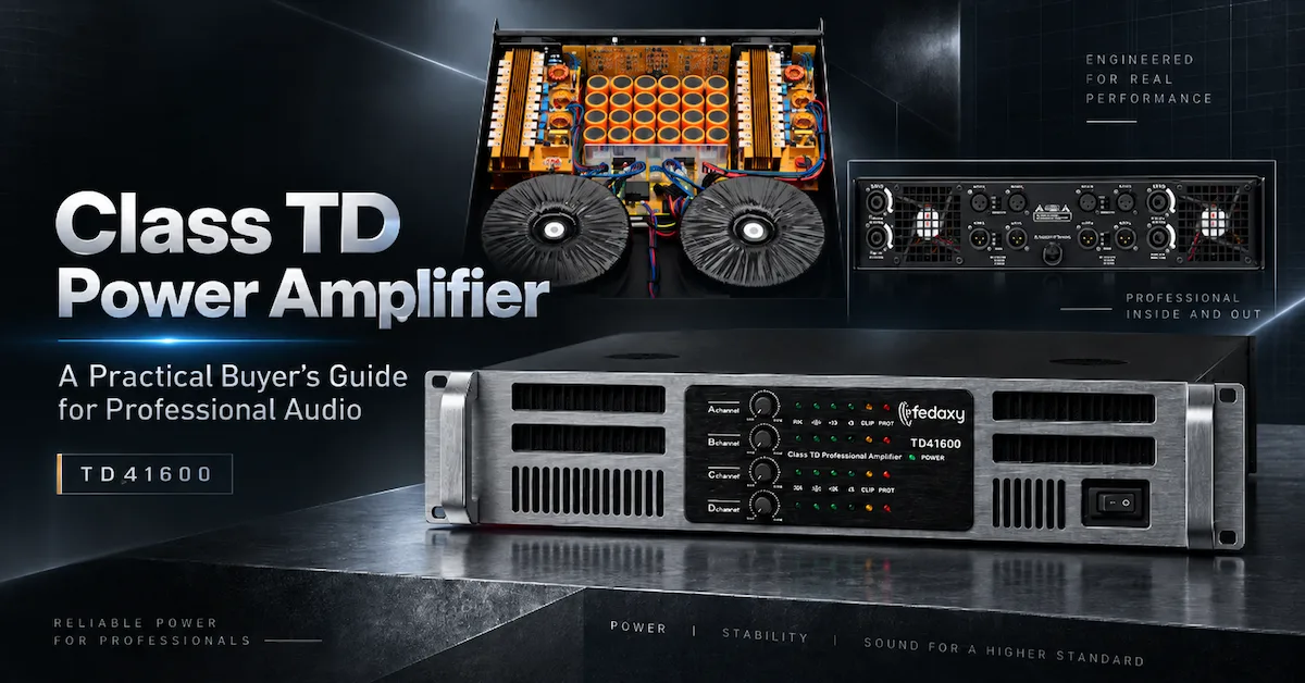
Published specifications for the Fedaxy TD41600
The current TD41600 product page lists four channels in a 2U chassis. Here are the main figures, as published by Fedaxy:
| Specification | TD41600 |
|---|---|
| 8-ohm output | 4 × 1,600 W |
| 4-ohm output | 4 × 2,400 W |
| 2-ohm output | 4 × 4,000 W |
| 8-ohm bridged output | 2 × 4,800 W |
| Specified AC input | 200–260 V, 50–60 Hz |
| Selectable sensitivity positions | 0.775 V / 1.0 V / 1.4 V |
| Cooling | Two fans, front-to-rear airflow |
The row I'd resolve first is the mains range. There is no 120 V option in that published 200–260 V specification. If 120 V is what the rack has available, ask the factory for a compatible version and get its supply marking into the order. Changing the country of delivery doesn't, by itself, change the amplifier's voltage requirement.
For the power rows, request the test sheet that goes with the table. Was the figure taken at one frequency? How long was the signal applied, and how many channels were loaded? Where was the distortion cutoff? Keep the wall voltage beside the result as well. A short burst tells you about a short burst. For a rack running through an evening, I'd also want to know what happens once the chassis is hot.
Obtain the input-current data for the intended operation before choosing the power circuit; summing the output ratings won't give you normal wall consumption. The table here reproduces Fedaxy's published figures. It isn't a measurement report on a sample we've tested.
Give the sample a question to answer
For this example, the purchasing question is quite narrow: can the proposed amplifier run all four 4-ohm channels at the level the eight cabinets need? Specify the program and the length of the run with that output target, before the supplier sends a sample.
A useful bench note has enough detail to repeat the run: load, signal, wall voltage, room temperature, gain setting and driven channels. With suitable test equipment, establish the output at the agreed distortion limit. After that, put the sample into the proposed signal chain. A resistor bank won't reveal a wiring mistake in the speaker loom or the wrong preset in the processor.
Two useful entries on the test sheet are 'level after warm-up' and 'recovery from protection'. For the second one, ask whether cooling alone restores the channel or an operator must intervene. A hard-to-reach rack makes that a purchasing issue. Put the fault indication alongside it so the operator knows what the amplifier is reporting.
For the listening trial, use matched levels. Take a seat near the proposed rack with the music muted as well. Mechanical fan noise won't appear in a signal-to-noise specification.
Keep the sample identity and results with the order. Leave deliberate fault checks to qualified technicians using the maker's approved procedure and suitable equipment. A shorted output with no defined method leaves everybody arguing about what the test actually proved.
Draw the back of the rack
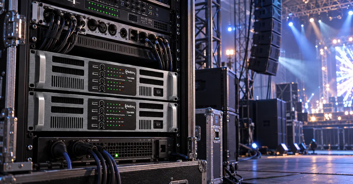
On the front drawing, a 2U amplifier is a neat rectangle. Behind it are plugs, cable bends, supports and the rear cover. Put those into the drawing too, with rear support as specified in the mounting instructions. Draw a replacement unit sliding out of the case. The loom needs enough movement for that job.
The air path doesn't end at the amplifier's rear panel. There must be somewhere for the discharge to go after it passes the connectors and loom. A closed rear cover is an obvious obstruction; a tight cupboard can be less obvious. Exhaust returning to the front intake is another problem to solve on the rack drawing.
Who will clean any fitted filters, and who will remove the chassis for service? Name the person in the handover. A cupboard location that makes those jobs awkward needs reconsidering before the rack is installed.
Set gain and speaker protection together
Here is a setting I would put in the handover file: input sensitivity. Suppose 0.775 V and 1.4 V are each specified for the same full output, as alternative positions. The lower input number means more gain.
The calculation is 20 log10(1.4/0.775) ≈ 5.14 dB. Below clipping, that can turn a hypothetical 50 V output into roughly 90 V for the same input when you select the more sensitive position. That is a substantial change at the speaker, even though nobody touched the processor's limiter. Measure the actual unit's gain, then put the switch position beside its limiter file.
Export the commissioned preset, including the speaker maker's prescribed filters and limiters, and reload it as part of the trial. Check the amplifier setting again afterwards. A spare can arrive on another sensitivity position while the processor still holds the old file. Keep that switch-setting note with the backup.
Touring, fixed installation and OEM orders
Touring buyers have to carry and patch the rack repeatedly. Weight, support, connectors and a quick spare swap all count. A nightclub is more likely to expose problems with long bass duty and a hot equipment room; the nightclub Class TD guide covers that application in more detail. In a fixed installation, independent zones, monitoring and replacement availability may lead the decision.
Label the bands on a multiway array's channel plan: subs, lows, mids and highs, wherever those divisions apply. Each has its own load and processing. For a zoned installation, make a second version with one rack crossed out. Seeing the silent zones on paper is a useful way to decide where redundancy or fault monitoring pays for itself.
A first inquiry can be plain: 'We have eight 8-ohm cabinets, two per channel. The rack has 230 V available. It will run bass-heavy program for the stated venue hours; here are the cabinet data sheets and processor settings. Which model and gain setting do you recommend?' Add the actual room conditions, features, quantity and destination. An offer based on another wiring arrangement belongs back on the drawing board. Resolve that with the supplier before comparing the price.
An OEM brief needs a little more care. Asking for a quieter fan sounds simple, but a substitute fan can move less air. Include the thermal trial when approving that change. Changing a connector brings the customer cable into the discussion; changing sensitivity brings the processor settings back in. Give the approved sample an identity that the factory and your service team can both follow. Service later on gets easier when the build number leads to a particular parts list and manual.
Before ordering
Can Class TD run subwoofers?
Yes, if the particular model supplies the necessary voltage and current into the planned load. Check low-frequency duty, filters and limiting with the actual cabinets.
What belongs in the purchase specification?
Keep the configuration you approved, its acceptance limits and the documents required for your destination market together. Include the warranty and repair route. For a custom build, identify the sample and how later revisions will be approved.
Technical references: Lab Gruppen's Class TD description explains its tracking-rail technology. IEC 60268-3:2018 is a measurement reference for sound-system amplifiers. Neither reference verifies another manufacturer's product ratings.
Conclusion
Come back to the eight cabinets and their wiring. That plan is now the basis for comparing a Class TD power amplifier: which unit can do this job, on this supply, with these settings? Take the sample's agreed configuration into the purchase order. For a recommendation, send Fedaxy the channel plan with your cabinet data sheets, venue conditions and required service arrangements.